

What Is A Linear Actuator Used For

Conceptual design of a bones traveling-nut linear actuator. Note that in this instance the pb spiral (greyness) rotates while the atomic number 82 nut (yellow) and tube (carmine) do not.

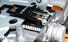
Floppy disc drive with leadscrew and stepper motor.
A linear actuator is an actuator that creates motion in a straight line, in contrast to the circular motion of a conventional electric motor. Linear actuators are used in machine tools and industrial machinery, in computer peripherals such as disk drives and printers, in valves and dampers, and in many other places where linear motion is required. Hydraulic or pneumatic cylinders inherently produce linear motion. Many other mechanisms are used to generate linear motion from a rotating motor.
Types [edit]
Mechanical actuators [edit]

A mechanical linear actuator with digital readout (a type of micrometer).

Roller screw actuation with traveling spiral (rotating nut).
Mechanical linear actuators typically operate past conversion of rotary move into linear motion. Conversion is ordinarily fabricated via a few simple types of mechanism:
- Screw: leadscrew, screw jack, ball screw and roller spiral actuators all operate on the principle of the simple car known as the screw. By rotating the actuator's nut, the screw shaft moves in a line.
- Wheel and beam: Hoist, winch, rack and pinion, chain drive, belt bulldoze, rigid chain and rigid belt actuators operate on the principle of the wheel and beam. A rotating wheel moves a cable, rack, chain or belt to produce linear move.[one]
- Cam: Cam actuators office on a principle like to that of the wedge, just provide relatively express travel. As a wheel-like cam rotates, its eccentric shape provides thrust at the base of operations of a shaft.
Some mechanical linear actuators only pull, such equally hoists, chain drive and belt drives. Others only button (such as a cam actuator). Pneumatic and hydraulic cylinders, or atomic number 82 screws can exist designed to generate force in both directions.
Mechanical actuators typically catechumen rotary motion of a control knob or handle into linear displacement via screws and/or gears to which the knob or handle is fastened. A jackscrew or car jack is a familiar mechanical actuator. Another family of actuators are based on the segmented spindle. Rotation of the jack handle is converted mechanically into the linear motion of the jack caput. Mechanical actuators are also ofttimes used in the field of lasers and optics to manipulate the position of linear stages, rotary stages, mirror mounts, goniometers and other positioning instruments. For accurate and repeatable positioning, index marks may be used on command knobs. Some actuators include an encoder and digital position readout. These are similar to the adjustment knobs used on micrometers except their purpose is position adjustment rather than position measurement.
Hydraulic actuators [edit]
Hydraulic actuators or hydraulic cylinders typically involve a hollow cylinder having a piston inserted in information technology. An unbalanced pressure applied to the piston generates a strength that tin can move an external object. Since liquids are nearly incompressible, a hydraulic cylinder can provide controlled precise linear displacement of the piston. The deportation is only along the centrality of the piston. A familiar instance of a manually operated hydraulic actuator is a hydraulic car jack. Typically though, the term "hydraulic actuator" refers to a device controlled past a hydraulic pump.
Pneumatic actuators [edit]
Pneumatic actuators, or pneumatic cylinders, are similar to hydraulic actuators except they utilise compressed air to generate force instead of a liquid. They work similarly to a piston in which air is pumped inside a sleeping accommodation and pushed out of the other side of the sleeping room. Air actuators are not necessarily used for heavy duty mechanism and instances where big amounts of weight are present. One of the reasons pneumatic linear actuators are preferred to other types is the fact that the power source is only an air compressor. Because air is the input source, pneumatic actuators are able to be used in many places of mechanical activity. The downside is, nearly air compressors are large, bulky, and loud. They are hard to send to other areas once installed. Pneumatic linear actuators are likely to leak and this makes them less efficient than mechanical linear actuators.
Piezoelectric actuators [edit]
The piezoelectric effect is a property of certain materials in which application of a voltage to the material causes it to expand. Very high voltages correspond to merely tiny expansions. Equally a effect, piezoelectric actuators tin reach extremely fine positioning resolution, but also have a very curt range of motion. In improver, piezoelectric materials exhibit hysteresis which makes information technology difficult to control their expansion in a repeatable manner.
Electro-mechanical actuators [edit]

A miniature electromechanical linear actuator where the lead nut is part of the motor. The pb screw does not rotate, so as the lead nut is rotated by the motor, the lead screw is extended or retracted.
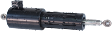
Typical compact cylindrical linear electric actuator
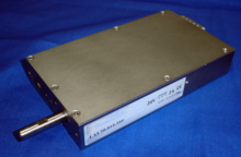
Typical linear or rotary + linear electric actuator
Moving coil linear, rotary and linear + rotary actuators at piece of work in various applications
Electro-mechanical actuators are similar to mechanical actuators except that the control knob or handle is replaced with an electrical motor. Rotary motion of the motor is converted to linear displacement. Electromechanical actuators may as well exist used to power a motor that converts electrical energy into mechanical torque. There are many designs of modern linear actuators and every company that manufactures them tends to have a proprietary method. The following is a generalized description of a very simple electro-mechanical linear actuator.
Simplified design [edit]
Typically, an electric motor is mechanically connected to rotate a lead screw. A lead screw has a continuous helical thread machined on its circumference running along the length (similar to the thread on a bolt). Threaded onto the lead screw is a pb nut or ball nut with corresponding helical threads. The nut is prevented from rotating with the pb screw (typically the nut interlocks with a non-rotating part of the actuator body). When the lead screw is rotated, the nut will be driven along the threads. The direction of motion of the nut depends on the direction of rotation of the lead screw. By connecting linkages to the nut, the movement can be converted to usable linear displacement. Nearly current actuators are congenital for high speed, high strength, or a compromise between the ii. When because an actuator for a item awarding, the virtually important specifications are typically travel, speed, strength, accuracy, and lifetime. Most varieties are mounted on dampers or butterfly valves.[three] [4]
In that location are many types of motors that can be used in a linear actuator system. These include dc brush, dc brushless, stepper, or in some cases, even induction motors. Information technology all depends on the awarding requirements and the loads the actuator is designed to move. For example, a linear actuator using an integral horsepower Air-conditioning induction motor driving a atomic number 82 screw can be used to operate a large valve in a refinery. In this case, accurateness and high motion resolution aren't needed, just loftier force and speed are. For electromechanical linear actuators used in laboratory instrumentation robotics, optical and light amplification by stimulated emission of radiation equipment, or X-Y tables, fine resolution in the micron range and high accuracy may crave the use of a fractional horsepower stepper motor linear actuator with a fine pitch lead screw. There are many variations in the electromechanical linear actuator system. It is disquisitional to sympathise the pattern requirements and application constraints to know which i would be best.
Standard vs compact structure [edit]
A linear actuator using standard motors volition unremarkably have the motor as a separate cylinder fastened to the side of the actuator, either parallel with the actuator or perpendicular to the actuator. The motor may be attached to the cease of the actuator. The drive motor is of typical construction with a solid drive shaft that is geared to the drive nut or drive screw of the actuator.
Compact linear actuators utilise peculiarly designed motors that try to fit the motor and actuator into the smallest possible shape.
- The inner diameter of the motor shaft tin can be enlarged, so that the bulldoze shaft can be hollow. The bulldoze screw and nut can therefore occupy the eye of the motor, with no need for additional gearing betwixt the motor and the drive screw.
- Similarly the motor tin be made to have a very small exterior bore, just instead the pole faces are stretched lengthwise and then the motor can withal take very high torque while plumbing equipment in a small bore space.
Principles [edit]
In the bulk of linear actuator designs, the basic principle of operation is that of an inclined plane. The threads of a lead screw act as a continuous ramp that allows a pocket-sized rotational force to be used over a long distance to reach the movement of a large load over a brusque distance. The power supply is from a DC or AC motor. The typical motor is a 12v DC, but other voltages are available. Actuators have a switch to reverse the polarity of the motor, which makes the actuator alter its motion.
The speed and force of an actuator depend on its gearbox. The amount of force depends on the actuator's speed. Lower speeds supply greater strength because motor speed and force are abiding.
One of the basic differences between actuators is their stroke, which is defined by the length of the screw and shaft. Speed depends on the gears that connect the motor to the screw.
The mechanism to stop the stroke of an actuator is a limit or micro switch, which can exist seen in the paradigm below. Microswitches are located at the top and lesser of the shaft and are triggered by the up and downwards movement of the screw.
Variations [edit]
Many variations on the basic pattern accept been created. Virtually focus on providing full general improvements such as a higher mechanical efficiency, speed, or load capacity. There is also a large engineering motility towards actuator miniaturization.
Most electro-mechanical designs contain a pb spiral and lead nut. Some use a ball screw and ball nut. In either case the screw may be connected to a motor or manual control knob either straight or through a serial of gears. Gears are typically used to allow a smaller (and weaker) motor spinning at a higher rpm to be geared down to provide the torque necessary to spin the screw nether a heavier load than the motor would otherwise be capable of driving directly. Effectively this sacrifices actuator speed in favor of increased actuator thrust. In some applications the use of worm gear is common as this allow a smaller congenital in dimension even so assuasive swell travel length.
A traveling-nut linear actuator has a motor that stays attached to ane end of the lead screw (perhaps indirectly through a gear box), the motor spins the pb screw, and the lead nut is restrained from spinning and so it travels up and downwards the pb spiral.
A traveling-spiral linear actuator has a lead screw that passes entirely through the motor. In a traveling-screw linear actuator, the motor "crawls" up and down a lead screw that is restrained from spinning. The only spinning parts are inside the motor, and may not be visible from the outside.
Some lead screws have multiple "starts". This means they have multiple threads alternating on the same shaft. I way of visualizing this is in comparison to the multiple color stripes on a candy pikestaff. This allows for more adjustment between thread pitch and nut/spiral thread contact expanse, which determines the extension speed and load conveying capacity (of the threads), respectively.
Static load capacity [edit]
Linear spiral actuators can have a static loading capacity, pregnant that when the motor stops the actuator essentially locks in place and tin support a load that is either pulling or pushing on the actuator. This static load capacity increases mobility and speed.
The braking force of the actuator varies with the angular pitch of the spiral threads and the specific design of the threads. Acme threads have a very high static load capacity, while ball screws have an extremely low load capacity and tin can be nearly free-floating.
By and large information technology is not possible to vary the static load capacity of screw actuators without additional technology. The spiral thread pitch and drive nut design defines a specific load capacity that cannot be dynamically adjusted.
In some cases, high viscosity grease can be added to linear screw actuators to increase the static load. Some manufacturers use this to modify the load for specific needs.
Static load capacity can be added to a linear screw actuator using an electromagnetic brake system, which applies friction to the spinning bulldoze nut. For example, a leap may exist used to apply brake pads to the bulldoze nut, holding information technology in position when power is turned off. When the actuator needs to be moved, an electromagnet counteracts the leap and releases the braking force on the drive nut.
Similarly an electromagnetic ratchet mechanism can be used with a linear spiral actuator so that the bulldoze organisation lifting a load will lock in position when power to the actuator is turned off. To lower the actuator, an electromagnet is used to counteract the spring force and unlock the ratchet.
Dynamic load chapters [edit]
Dynamic load capacity is typically referred to as the amount of strength the linear actuator is capable of providing during operation. This force will vary with spiral type (amount of friction restricting motility) and the motor driving the movement. Dynamic load is the figure which most actuators are classified past, and is a skilful indication of what applications it would suit best.
Speed command [edit]
In nearly cases when using an electro-mechanical actuator, it is preferred to accept some type of speed control. Such controllers vary the voltage supplied to the motor, which in plough changes the speed at which the lead screw turns. Adjusting the gear ratio is some other style to accommodate speed. Some actuators are available with several different gearing options.
Duty bike [edit]
The duty cycle of a motor refers to the amount of time the actuator can be run before it needs to absurd down. Staying within this guideline when operating an actuator is key to its longevity and operation. If the duty bicycle rating is exceeded, and so overheating, loss of power, and eventual burning of the motor is risked.
Linear motors [edit]
A linear motor is functionally the aforementioned as a rotary electrical motor with the rotor and stator round magnetic field components laid out in a straight line. Where a rotary motor would spin around and re-utilize the same magnetic pole faces again, the magnetic field structures of a linear motor are physically repeated across the length of the actuator.
Since the motor moves in a linear fashion, no lead screw is needed to convert rotary motion to linear. While loftier chapters is possible, the material and/or motor limitations on almost designs are surpassed relatively quickly due to a reliance solely on magnetic attraction and repulsion forces. Virtually linear motors take a depression load capacity compared to other types of linear actuators. Linear motors have an advantage in outdoor or dirty environments in that the two halves practice not demand to contact each other, then the electromagnetic drive coils tin exist waterproofed and sealed against moisture and corrosion, allowing for a very long service life. Linear motors are being used extensively in high performance positioning systems for applications which require various combinations of high velocity, loftier precision and high forcefulness.
Telescoping linear actuator [edit]
Telescoping linear actuators are specialized linear actuators used where space restrictions be. Their range of move is many times greater than the unextended length of the actuating member.
A common form is made of concentric tubes of approximately equal length that extend and retract like sleeves, one within the other, such as the telescopic cylinder.
Other more specialized telescoping actuators utilise actuating members that deed as rigid linear shafts when extended, simply interruption that line by folding, separating into pieces and/or uncoiling when retracted. Examples of telescoping linear actuators include:
- Helical band actuator
- Rigid belt actuator
- Rigid concatenation actuator
- Segmented spindle
Advantages and disadvantages [edit]
| Actuator Type | Advantages | Disadvantages |
|---|---|---|
| Mechanical | Inexpensive. Repeatable. No power source required. Self-independent. Identical behavior extending or retracting. | Manual operation only. No automation. |
| Electro-mechanical | Cheap. Repeatable. Performance can be automated. Cocky-contained. Identical behaviour extending or retracting. DC or stepping motors. Position feedback possible. | Many moving parts prone to wear. |
| Linear motor | Simple blueprint. Minimum of moving parts. Loftier speeds possible. Self-contained. Identical behavior extending or retracting. | Low to medium force. |
| Piezoelectric | Very pocket-size motions possible at high speeds. Consumes barely any ability. | Short travel unless amplified mechanically. High voltages required, typically 24V or more. Expensive, and fragile. Proficient in compression but, not in tension. Typically used for Fuel Injectors. |
| TCP: Twisted and coiled polymer | lite and cheap | Low efficiency and High temperature range required |
| Hydraulic | Very high forces possible. Relatively high power to size ratio (or power density). | Tin leak. Requires position feedback for repeatability. External hydraulic pump required. Some designs good in compression just. |
| Pneumatic | Strong, lite, simple, fast. | Precise position control impossible except at full stops |
| Wax motor | Smoothen operation. | Not as reliable equally other methods. |
| Segmented spindle | Very compact. Range of motility greater than length of actuator. | Both linear and rotary move. |
| Moving coil | Strength, position and speed are controllable and repeatable. Capable of high speeds and precise positioning. Linear, rotary, and linear + rotary actions possible. | Requires position feedback to be repeatable. |
| MICA: Moving iron controllable actuator | Loftier force and controllable. Higher force and less losses than moving coils. Losses easy to dissipate. Electronic driver easy to design and set. | Stroke limited to several millimeters, less linearity than moving coils. |
See too [edit]
- Helical ring actuator
- Hoist – Device used for lifting or lowering a load
- Rack and pinion – Type of linear actuator
- Solenoid – Blazon of electromagnet formed by a ringlet of wire
References [edit]
- ^ Sclater, N., Mechanisms and Mechanical Devices Source book, 4th Edition (2007), 25, McGraw-Loma
- ^ "Underwater Linear Actuator". Ultra Move.
- ^ "Linear Actuator Guide", Anaheim Automation, retrieved May 12, 2016
- ^ "Electric Actuators", Baelz Automatic, retrieved May 12, 2016
External links [edit]
- Leo Dorst's Lego linear actuator

What Is A Linear Actuator Used For,
Source: https://en.wikipedia.org/wiki/Linear_actuator
Posted by: pricewhave1982.blogspot.com
0 Response to "What Is A Linear Actuator Used For"
Post a Comment